Off-line linearly regulated supplies are traditionally bulky, heavy and inefficient. With 60Hz magnetics providing the safety isolation barrier, the first two items are unavoidable; the latter problem is not. Post regulation can be provided by nonlinear switching regulators, but in a laboratory where noise is possibly critical, fairly efficient linear regulation is not impossible.
Some commercial low-power lab supplies switch the transformer secondary winding or rectifier configuration, in step with the output voltage adjustment setting, with an audible clicking. Those who mistrust the longterm reliability of this electromechanical method may wonder just how long this is intended to provide trouble-free service. A solid-state version is described below.
In the 80's and 90's, large multiple-output linear computer power packs were dumped onto the surplus market, as switching power products replaced them. One such device from NCR sported ferroresonant preregulation of windings for +/-5, +/-12 and 24V outputs, all with hefty current ratings, as well as numerous auxiliary isolated control voltages. The power rectifiers could easily be reconfigured to provide multiple series voltage cells with 12, 15 and 24V outputs.
With the higher-current windings on the grounded end of the string, a linear control circuit could be configured so as to draw from the series string, cutting out the higher voltage cells as the regulation range was reduced. In this way the losses in the series pass regulation element never exceeded those of a single voltage cell.
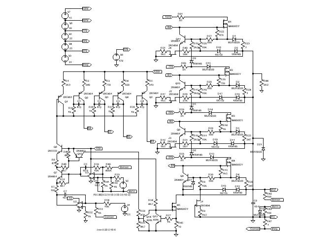
The conceptual schematic below shows this application in a more modest 2Amp regulator.
In the actual application, the mosfet pass elements are actually used to drive high power bipolar transistors instead of the output diodes illustrated here, allowing regulation at 10A in the higher voltage ranges and increased current in the lower voltage ranges. Function of the lower-powered demonstration is illustrated in simulator waveforms below.
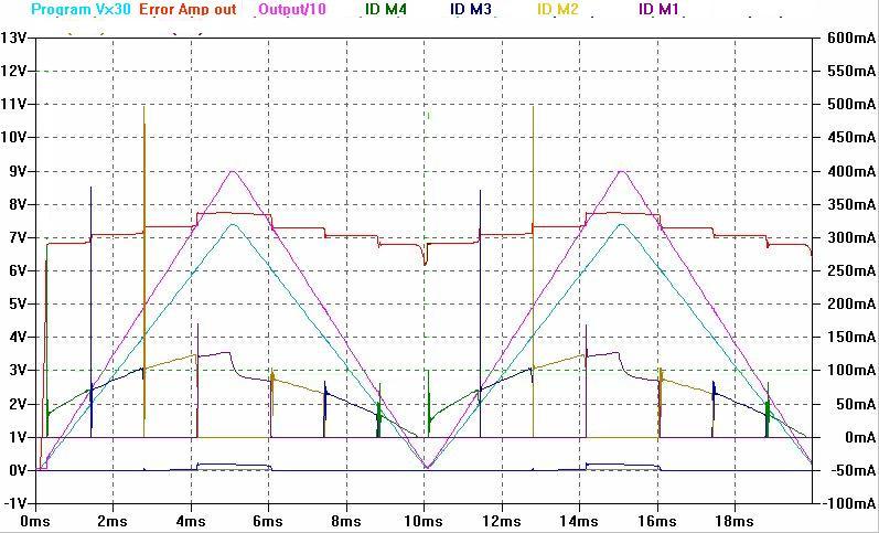
Note that as the output voltage is programmed to rise through each region to 90V, the respective pass transistors naturally assume the regulatory role. Losses in the pass element are limited to Vsection x Iout at the worst case. As a DC regulator, it is not normally expected to sink current, however the same configuration of switched pass transistors would produce similar results in that function, if required. In this demonstration, a switched load is provided to discharge filter capacitors.
This lower-powered section of the circuit is seen represented in the hardware below, by the control circuit board. Fets are mounted on the heatsink and are free-air convection cooled.
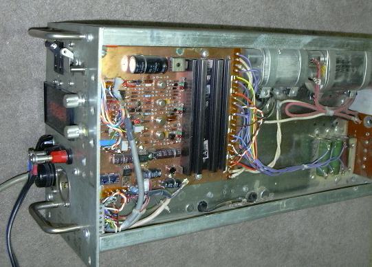
There are a number of locations in the circuit where led status indicators can naturally be located, without affecting circuit operation, to indicate regulation mode, operational regulator stage, or fault limiting.
The higher-powered pass elements use hardware from the original supply, with suitable rectifiers, transistors and sense resistors substituted. These get a fan, as did the originals, though thermal rises are modest.
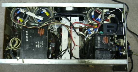
Metering is added, to display setpoint and measured voltage, current or crowbar levels.
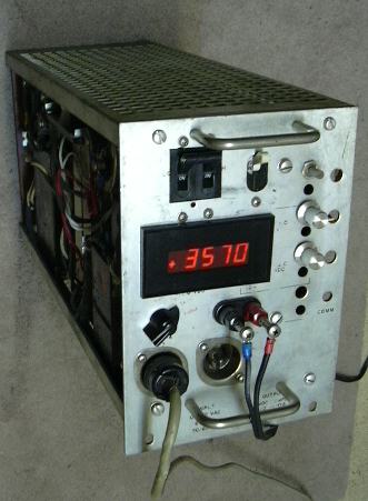
It's still weighs as
much
as a boat anchor, but at least now it pays it's way.
A SwCadIII model of the lower-powered example is available here.