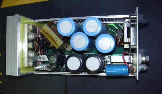
With three profiles of new case extrusions for the GSFL closed frame product already sitting in the warehouse, I generated the prototypes to fill them. The fact that only two of the three outer-wall cover extrusions were necessary to produce the three sizes intended was immediately obvious.
Metal power transistors were still prejudicially expected in the main power train (as well as still actually being cheaper, at that time); so too were 'computer-grade' electrolytics with screw terminals. No fans were permitted. At least for the 250W and 350W versions, these factors determined the main mechanical problems to be inherited, along with the box.
The higher power solution was one wave-solderable assembly (the same for all models with the same power level) on which a capacitor-bussbar assembly was mounted. The power transistors mated with wave-soldered sockets. The power transformer, output rectifiers and choke still had to be hand-soldered or crimped and hardwired. The bussbar assembly and input terminal filter board assembly, with its adjustment, indicator and interface function, was characteristic of the model - determining the output voltage. The bussbar provided it's own output terminals, but the input terminal assembly, though harness free, still required that the terminal block and captive faceplate be manually soldered.
Maintaining safety clearance under
the encroaching 0804 standards was achieved by careful planning at the
earliest stages, on paper, to avoid adding insulators to the surrounding
walls. Advertised claims of output terminal isolation of 500VDC were just
as demanding. Remember that these were convection cooled units without
built-in fans - air movement could not be impeded without impairing function.
The isolation barrier to the heatsink was one flat isolator on the exruded
fin surface, serving both the primary switches and the output rectifiers.
The epoxy-coated input rectifier bridge was also allowed to contact the
box wall, though the actual surface temperature rise of the covers had
to be limited to safe values.
Control power was developed by an isolated synchronized converter. The new UC3847 control IC was used in voltage mode with current feedforward and average current limiting, allowing heavy peak-to-average operation. Output overload protection was fold-back, with a timed shut-off that was only entered under conditions approaching short circuit. The output could be adjusted and the limiters or latches enabled or reset either manually through the front panel (without breaching the 500V isolation barrier), or remotely through the control harnessing. Multiple units could be both synchronized and paralleled under forced current sharing.
The 150W assembly was entirely wave solderable and required no bussbar. Trying this later arrangement for 250W units with a higher output voltage, was also demonstrated.
Note the use of extended-creepage optocoupler bodies. While these were an admirable attempt at meeting the letter of the law, with regards to the VDE creepage requirements, their thermoplastic construction turned out to be quite flammable. This was 'luckily' discovered under 'abuse' testing - blocking all convection air holes and seeing how long the device ran without thermal limiters. An eventual failure in the little housekeeping supply resulted in an overloaded resistor, igniting an optocoupler body.
After repair (what mess!), the test unit continued it's trials without other component replacements. The actual failure mechanism was traced to a temporary socket, used (only on that unit particular evaluation unit, of course) to mount the housekeeping transformer. The larger lesson in this case was that any kind of accellerated stress testing has to use normally-processed parts to obtain meaningful results.
Testing of the initial model -
a 350W 5V unit - had just been completed and preproduction kits assembled
when this program was stopped and the engineering department staff cut
by a third. I was switched over to the linear supplies, which were also
showing performance and cost problems related to their original design.