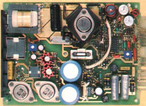
This used mosfets ($) in a half-bridge inverter and standard CMOS ICs to generate the control functions. The power mosfet transformer gate drive was powered from the HVDC input bus, control power was capacitor bleeder current alone; output error signals were generated by a zener diode and a two-transistor long-tailed pair.
This switcher, my first ever, was completed as a student project submission in the George Brown Electronic Technology program. Unfortunately, the project choices for that specific year only included an automated phone dialer and one another similarly fascinating device. Apologies to Mr. Kimmel - but the research portion of this project was completed in a previous program year, before the rapidly changing program format was firmed up. As a result, it wasn't marked very highly, but it's existence was probably the main reason I was taken on strength, later, at Hammond.
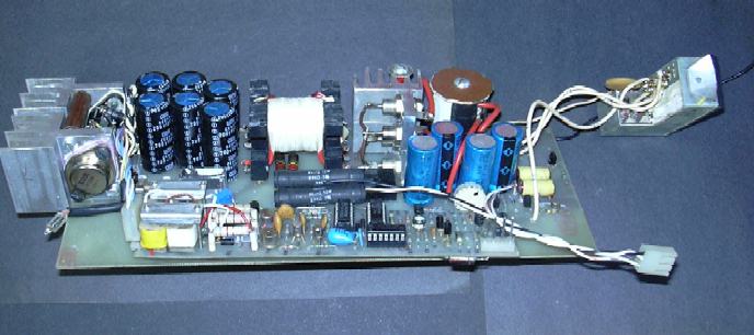
Note the hand-made 'litz' wire in both the main transformer and gapped-ferrite pot-core inductors. Without impregnation, these rustled like dry wind-blown grass, and rang like bells under output load transient stimulation. The EC power transformer core set was scavenged for other work, at some later date. The 'modified' bobbin was needed to meet a self-imposed 2" height restriction. The footprint was intended to fit into a slot at the end of a low profile rack-mounting assembly.
The work was mostly inspired by a magazine
article describing the resonant FM switching power modules being developed
and marketed by HP - where they were not only fabricating their own mosfets,
but even ended up rolling their own resonant film capacitors, as well;
just to deliver a modest 75W output. Ouch. This made me dubious of the
practicality of resonant power converters for many years to come.
The project unit was, of course,
not resonant, or it would never have developed 250W continuous output,
even with the modest currents that the +/- 45V outputs produced. In spite
of (or more possibly because of) the difference in height and topology,
power density was four times that of the HP unit. Although not the best
of engineering practices, the materials and hardware in it were scavenged
from local junk sources, except for the horrendously expensive mosfets.
These were the only ones left in stock on the day of purchase, out of the
extensive range advertized - some recommendation! Berylium oxide transistor
insulators are considered as hazardous material nowadays and were only
used then because they were what was available.
Constant pulse-width, constant output ripple control methods were adopted by a number of companies producing low-power integrated switchers, for a short time, due to its relatively simple control characteristics, inherent stability and rapid dynamic response. If you must use frequency modulation, better noise and efficiency is achieved nowadays over a wide range of power levels with critical conduction, than was ever achieved with resonant or fixed pulse width topologies. You could, however, hit the oscillator or other control functions in this one with a heat gun, without affecting it's open-loop behavior.
The blown-fuse indication (a tacked-on neon) could be achieved at about 400W output at low line, without fets or anything else popping. It was only later that I learned how uncommon this is viewed to be, in prototyping. I personally consider it to be a basic requirement for validation, otherwise supervisory overload or overtemperature circuits that are added later may be pointless.